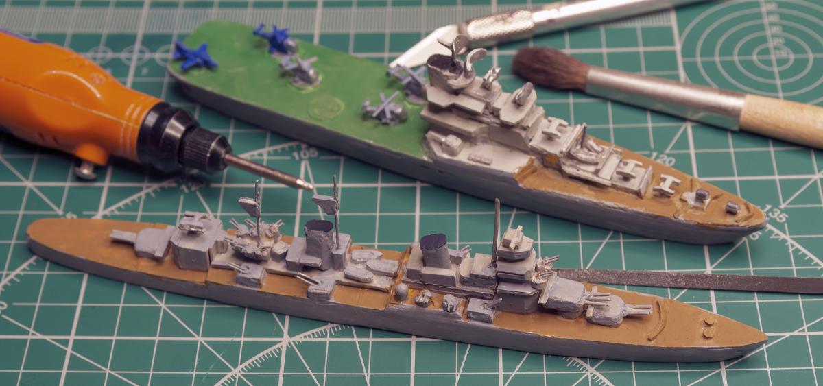
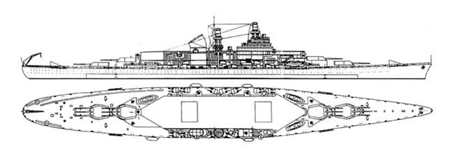
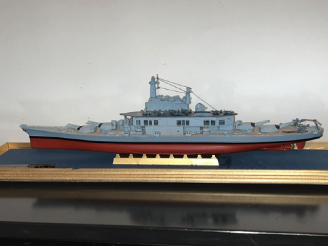
In the 2022 February issue of Naval History, Jack Russell reported on an imaginary ship released in an October 2021 update for the World of Warships online multiplayer game. Named the USS Kearsarge, this battleship/aircraft carrier hybrid, based on a 1937 plan developed for the U.S. Navy by the firm of Gibbs and Cox, could potentially have seen service during World War II (see Figure 1). The ship was originally commissioned by the Soviet government and the U.S. Navy only showed interest later to keep the Soviets from obtaining such a powerful warship. Those plans were abandoned when the emphasis shifted to true aircraft carriers, and the hybrid ship was never built.
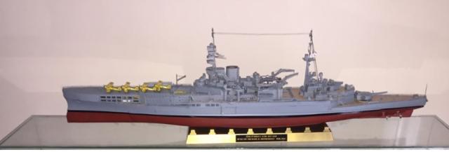
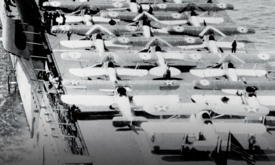
The concept of combining a battleship with an aircraft carrier dates to the 1917 Royal Navy conversion of the HMS Furious, originally ordered as a battlecruiser armed with two 18-inch guns. A flight deck was fitted forward before completion, with an underlying hanger deck and lift, in place of one of the 18-inch guns (see Figure 2).
Displacement as an aircraft carrier was 22,450 tons, with an overall length of 786 feet, 3 inches. However, the design was not entirely successful, and changes were made, first removing the aft gun and eventually the entire superstructure. As a true “flattop,” the Furious served well in World War II. I replicated this effort, converting a plastic kit of the HMS Repulse into the initial design of the HMS Furious by removing the forward gun, inserting a hanger deck, and adding a forward flight deck. In 1/350 scale, the model is 27 inches long.
Japanese aircraft carriers were conversions originally designed as battleships, though none retained their battleship armament, and all were sunk during World War II. The largest was the Shinano, the third of the Yamato-class. In 1944, partially under construction as a battleship, she was en route to Kure naval base when sunk by torpedoes from the U.S. Navy submarine USS Archerfish (SS-311).
While the Saratoga and the Lexington began construction as battle cruisers, they were converted to complete aircraft carriers in the 1920s. The U.S. Navy never attempted a partial conversion of battleship to aircraft carrier, although interest in the concept had remained to some extent. In the mid-1930s, Gibbs and Cox delivered three different designs of a battleship-aircraft carrier hybrid, possibly to be built for the Russian and U.S. Navies. Project A was to be 66,074 tons displacement, with eight 18-inch guns and 40 planes; Project B was to be 71,859 tons displacement with 12 16-inch guns and 40 planes; and Project C was to be 44,200 tons displacement with ten 16-inch guns and 28 planes. Although there was interest in this project by possible conversion of a 920-foot-long Montana-class battleship, construction was cancelled in favor of expanding the construction of Essex-class carriers in World War II. Building a model of the Gibbs hybrid ship was an exciting challenge.
Choosing the Scale and Kits
While 1/350 scale kits of the Montana-class are available in the United States, my wife would not be happy with an 80-cm-long monster in the house! A kit of the never built BB-71, the USS Louisiana, is available, and I chose to use that as a basis for my model conversion of the Gibbs and Cox design B. At 1/700 scale, the 40-cm-long model is not widely available in the United States. I purchased one from a firm in Australia.
Building the aircraft carrier part requires using parts from an aircraft carrier kit. I used a kit I already had of the USS Yorktown (CV-10), although any Essex-class carrier would work.
Building the Ship
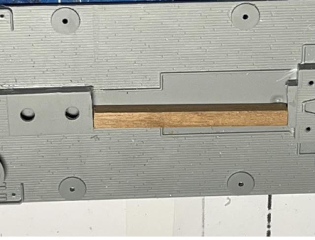
The first step in building the model is producing a plan, by enlarging the drawing in the Russell article to a 40-cm (16-inch) long 1/700 scale. It is useful to keep the plan on the workbench throughout. Unless indicated otherwise, all parts numbers are from the Louisiana kit. It becomes apparent that the 16-inch gun stern turrets must be placed five centimeters toward the stern, which is done by cutting part D12, the upper gun deck and placing a central 5-cm insert (see Figure 3).
The base for the lower stern turret must be removed from the main deck. I did this by drilling and connecting a series of holes around the base, sanding it to the correct thickness, and installing it on the quarterdeck, lining it up with the plan.
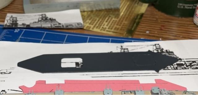
The flight deck is copied from the plan and cut out, first in card stock to check the fit, then out of the plastic carrier flight deck, and then painted (see Figure 4).
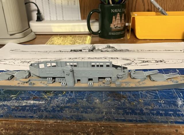
The bridge parts G 9, 10, and 11 are glued together and placed on the main deck, fitted into G13. The hanger deck (Figure 5) is cut out of the carrier flight deck, again first in card stock (red in Figure 4) and taking care to have the elevator properly aligned, is elevated above the main deck using part G13, and placed toward the stern by matching the shape to the overlying flight deck.
This deck is also supported underneath by parts D17, G13, and other parts at the same height. The hanger deck sides are built using solid parts from the carrier kit. Carrier parts 8, 9, and 10 raise the overlying flight deck above the hanger deck. These parts have rectangular openings, allowing one to see aircraft on the hanger deck. The flight deck can then be placed (see Figure 6).
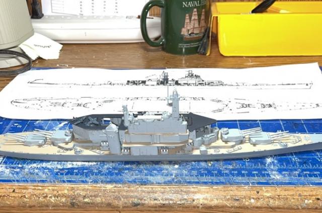
The island is built from the carrier parts, offset to the starboard. A platform for the island is built in two levels, first from the main deck to the hanger deck using carrier parts and then up to the flight deck, using carrier parts A 3, 5, and 6. Parts from the battleship superstructure and masts are added (see Figure 7) with a small piece of the flight deck trimmed to the right size and fitted between the masts. The battleship stack is raised by adding stack parts from the bottom of the carrier stack.
Parts from the carrier kit are trimmed and cut to the right height to raise and match the island to the flight deck. Island decks are painted in deck wooden tan. Planes are added to the hanger and flight decks (see Figure 6). The aircraft I used are those in the carrier kit. It is necessary to fold the wings to fit the planes in the elevators and in the hanger deck, where the planes are visible. I chose to open the forward elevator, placing a plane underneath.
The Louisiana kit includes a large sheet of photoetch railings and other parts, which can be used as wished. The next step is adding the various guns from the Louisiana kit, as well as the placement of the lifeboats and a modest amount of rigging as seen in the plan.
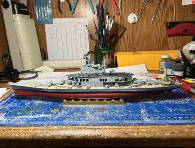
The final construction step is adding the hull section below the waterline. Painting is the modeler’s choice. I used shades of gray; dark for the flight deck, medium for the hull, and light for the superstructure; and dull red below the waterline. The black waterline is most easily done using black plastic adhesive striping tape available from automobile stores, trimmed down to the right size. Mounting the model on a suitable stand on a Navy-blue base with gold trim (see Figure 8) results in a replica of a ship the U.S. Navy never built.


